Usual Disclaimer: Information here
is not necessarily the "Truth", but it's the best information I have.
If in doubt about any step, verify with some other source. If
anyone sees something wrong, please let me know. rawham (at)
wham.org
Important: In the
instructions, please note - "rear" refers to the rear of the tractor.
"Front" is towards the front of tractor. "Right" and "left"
are in reference to the right and left of the tractor. You
will be making the adjustments from the rear, well above the PTO
shaft
end. The start/run band adjustment will be the front one,
(farthest away from you.) I have added some labels to figure 38 from Tractor
Manual for reference.
If you have a friend with long, thin, strong, flexible
fingers ask
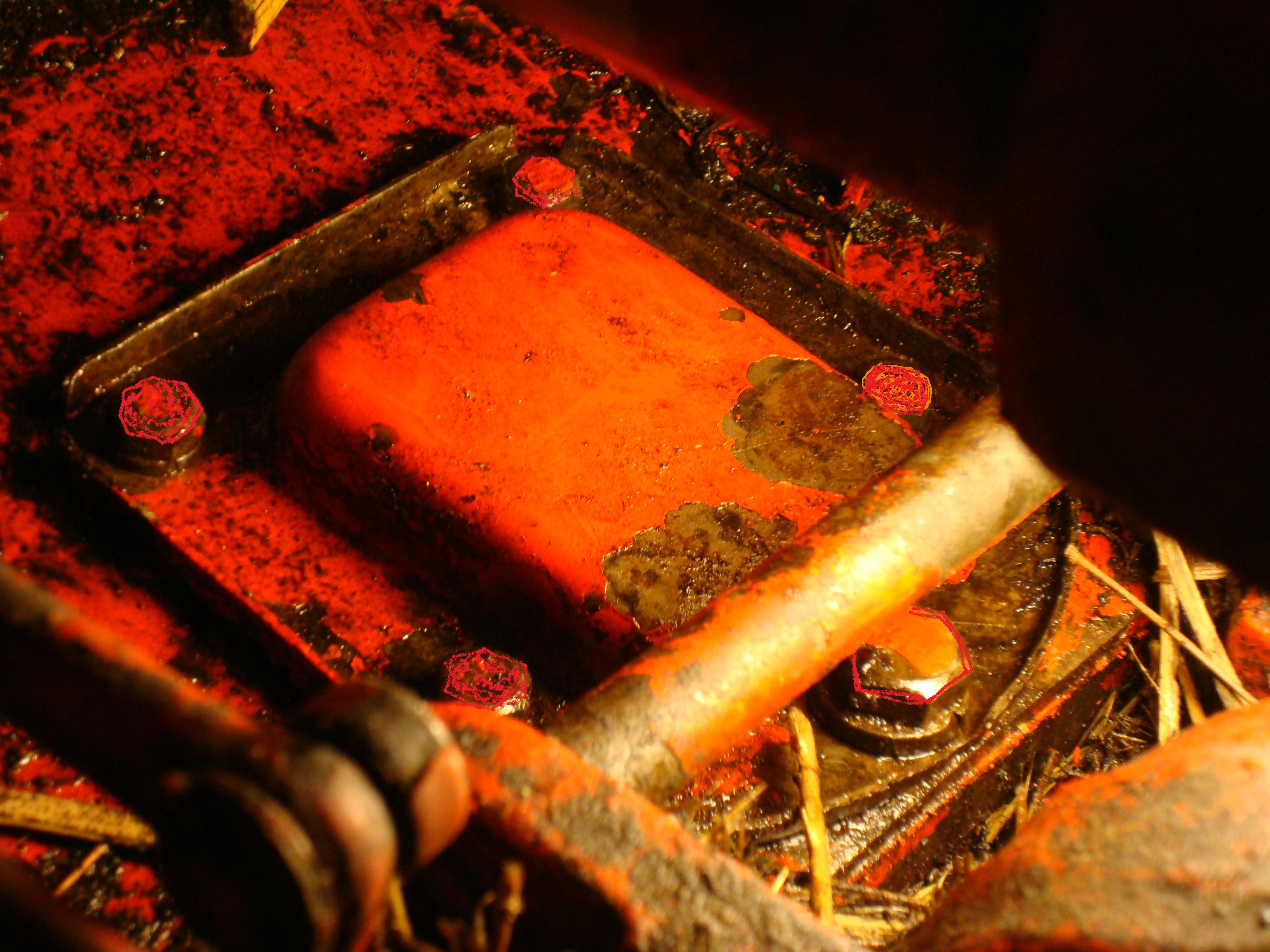
him/her for help. To access the adjustment screws/shafts, you
must remove a small rectangular plate about three by four inches.
The
plate is raised in the center.
There is a small bolt at each corner and and an
additional larger bolt at the rear of the plate. The access
plate
is horizontal, above the PTO shaft, between the raised portion of
the gas tank and under the rear portion of the main lift cylinder.
Photo of plate taken from left
- rear . Bolts have been touched up for better detail.
It's
not easy to get into the area to do the work! Lower the
rear hitch, and remove the pin that attaches the rear portion of
the main lift cylinder. Prop up/tie up the
cylinder rear end to get it out of the way as much as possible.
Next is the
hard part: (See above advice about long flexible
fingers.) Remove the bolts and
remove the plate. You will see the top
of two adjustment screws/shafts sticking up. See Figure 38.
The front one (the one farthest away from you) is the one
that controls the start/run bands.
Below is the method of adjustment as printed in the Tractor
Manual (except for my additions in
italics).
In my opinion,
this appears to be suitable if the system has been
completely rebuilt or taken apart, and this describes the first time
adjustment.
If your PTO is slipping under load, I would only adjust the
start/run band as necessary.
To begin, (See Step 1. below.) the
PTO shaft control lever must be placed in the
middle slot
of the quadrant (item 7, figure 38).
The hole ( 31, figure
38) must
be lined up with a hole in the housing and a bolt placed to hold
it in this "neutral" position during the adjustment. Find a bolt
that is snug, but it does not need to be threaded in, only placed in
far enough to prevent forward/backward motion of the lever. See
Step 1. below.
Before Step 2. you must lower
the hitch and get the cylinder out
of the way as described above. After you have removed the access
plate, then what I have done, is to turn
the front screw (the one away from you) in (clockwise) one turn.
Then remove the bolt holding the control lever in center
position. Move the lever forward to engage the PTO run position.
It should be firm and snap in the foreword position.
If it goes into the forward lock position without much
pressure, then reinsert the
bolt, and turn the forward adjust screw in another one half turn.
Test again. Keep advancing until it takes considerable
pressure to lock forward in running position. If unable to
advance all the way forward, then back the adjustment screw off
slightly, until able to properly lock forward in running
position. After final adjustment, replace everything into
original condition. Don't forget to remove lever stabilization
bolt.
Adjustment of Rear
Power Take-Off Control System
Copied from Belarus Manual
"Brakes" as used below refers to the PTO bands.
Start of Copy:
The rear power take-off control system (see Fig. 38) needs
adjustment
of the reduction gear brakes and control linkage rod which is effected
in the following manner: Link to
pdf file of Figure 38 from Tractor
Manual - Print for reference
1. Bring the hole in the shaft lever to register with the threaded hole
in the rear axle housing and fix the lever in this position by screwing
the bolt M10X60 mm in.
2. Remove the cover from the adjusting port and turn in the adjusting
screws as far as they go: turn the screws one by one, applying a torque
of 0.8—1 kgf-m. Then back every screw out by three turns.
3. Remove the PTO cap if it was not removed beforehand, and check the
PTO shaft for easy rotation by turning its tail end by hand. If
rotation proves to be tight, back the screws out by another half a turn.
4. Make sure that the control lever is in neutral position (in the
middle slot of the quadrant) with the shaft lever in the fixed
position. If necessary, change the length of the linkage rod to obtain
this condition. Having done this, turn the bolt out and reinstall all
the parts removed.
In service the factory adjustment gets disturbed because of the wear of
the brake band linings. As a result, the brakes fail "to hold", i. e.
they start to slip. Never go on working with the brakes slipping.
If any signs of slipping are noted, remove the cover and turn each
adjusting screw in by half a turn.
End of section.
Home